For any home project, be certain to follow local code and permitting requirements.
© 2022 Trex Company, Inc.
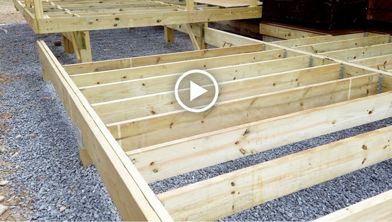
01. Intro
02. Determine Ledger Location
03. Establish Beam Height
04. Support Post Install
05. Mark Post for Bottom of Beam
06. Post-to-Beam Connections
07. Cutting the Posts
08. Chemical Treatment
09. Beam Install
10. Backfill Post Holes
11. Post-to-Beam Bracing
12. Add Beam Tape
13. Recap
Step-by-Step Instructions
- 01: Ledger Board Placement at the House
- 02: Types of Deck Beam to Post Connections
- 03: Marking and Cutting the Notch in a 6x6 Post
- 04: Find the End of the Beam Where the Deck Edge Will Start
- 05: Cutting and Installing the Beam
- 06: How to Attach the Beam to the Post
- 07: Lateral Bracing
- 08: Beam Tape Installation
Chapter 01: Ledger Board Placement at the House
Print This Chapter
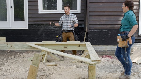
So you're ready to get started? Watch our how-to tutorial before you start your build.
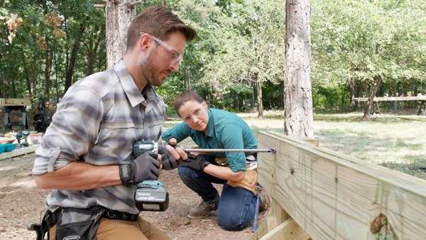
Before you begin any DIY project, make sure to wear the appropriate personal safety equipment. Eye protection, ear protection, gloves, long pants, a long-sleeved shirt, and reinforced toe shoes are recommended. Always make sure that you have a first aid kit nearby. For any home project, be certain to follow local code and permitting requirements.
Step 1
Ledger boards can be placed in two potential positions.
The first placement option entails placing the ledger board flush with the bottom of the door threshold. This placement option will result in the deck being even with the interior floor of the house for an even walk out. In areas where there is little snow, this can be a very attractive option.
The second placement option entails placing the ledger board below the threshold of the door. This creates a step down onto the deck when exiting the house. This step down cannot be less than 4” or more than 7 ¾” (per International Residential Code requirements) when measured to the top of the decking. When using this placement option, the ledger board is attached to the rim joist of the house. Be sure that all fasteners are in contact with the rim joist of the house and check with your local municipality to ensure that you are compliant with code requirements. This option can help prevent snow buildup at the door in areas that receive larger amounts of snow.
In this case, the original deck was built with a step-down from the house, so to maintain the height of the previous deck, the second placement option was used during this build.
Step 2
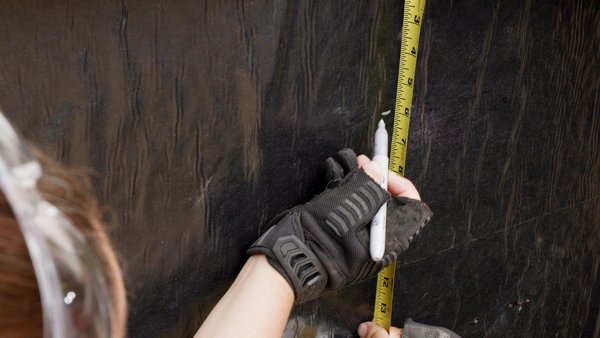
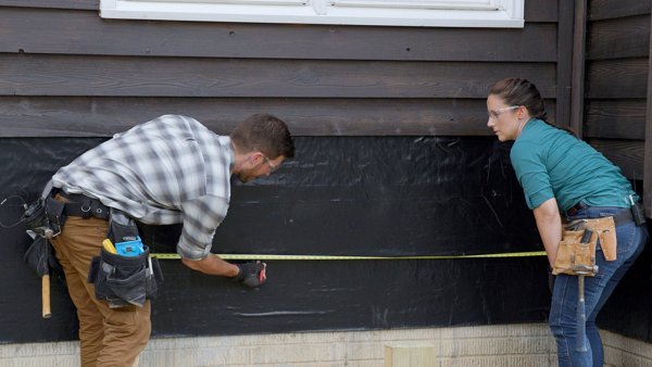
The municipality code for step height is measured from the top of the threshold of the door to the decking, and the maximum allowable height of the step is 7 ¾”. As you make your own step height measurement, be sure to stay under the maximum height requirement and mark the house to remember your distance. In this case, the desired distance of 6” was measured down from the door to the decking where a mark was made.
Step 3
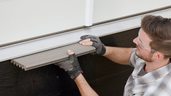
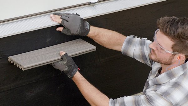
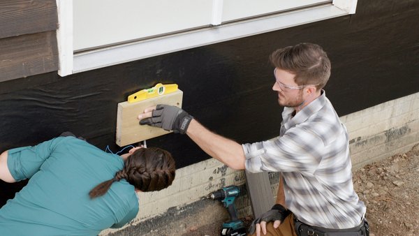
Hold a scrap piece of the decking to the mark placed on the house during Step 2. Make sure the piece of decking is level and make another mark under the piece of decking. This will be where the top of the ledger material is placed during installation.
Place a piece of scrap ledger material up to the new mark. In this case, the ledger material was 2x8 pressure-treated lumber.
Holding the scrap ledger material level, repeat the measurement process and make a mark under the scrap piece of ledger material. This mark will be used during the next installation step.
Step 4
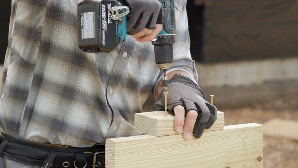
Attach a small piece of 2x4 material, 4”- 8” long, to the bottom of a piece of beam material. This 2x4 material will act as a helping hand in the upcoming installation steps.
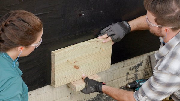
Hold the piece of scrap beam material, 2x10 pressure treated lumber in this case, up to the mark made under the bottom of the ledger material in the previous installation step.
Fasten the beam material to the wall with 3” exterior-grade wood screws. This piece is temporary so do not over-tighten the fasteners so it can easily be removed later.
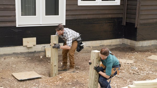
Drop the post into the hole on top of the footing. Refer to our Trex Academy guide “How to Install Deck Post Footings” for more information on digging the holes you’ll need here.
Pro Tip
Using 2x4’s, construct a stand that can act as a helping hand at various times throughout the project. Use two small scrap pieces of 2x4, around 24” long, and fasten them together in a ‘T’ configuration. Then fasten a longer piece, 36”- 48” long, vertically to the side of the ‘T’ shape.
Step 5
Find a long, straight edge to place from the ledger beam to the outer edge of the deck. This can be a 2x4 or a piece of the joist material. The only requirements are that the material is a) as straight as possible and b) long enough to reach the post that is being marked on the outer edge of the deck. The small piece of 2x4 attached to the beam material in Step 4 will be the ledge for one end of the straight edge. The other end of the straight edge will be held up by the stand that was built in the Step 4 Pro Tip.
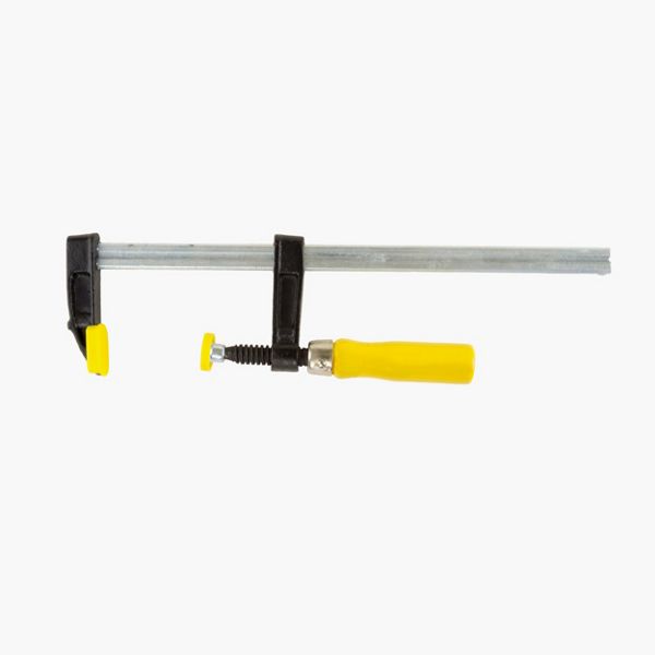
Place the straight edge on the 2x4 block, level it, and clamp it to the stand using a bar clamp.
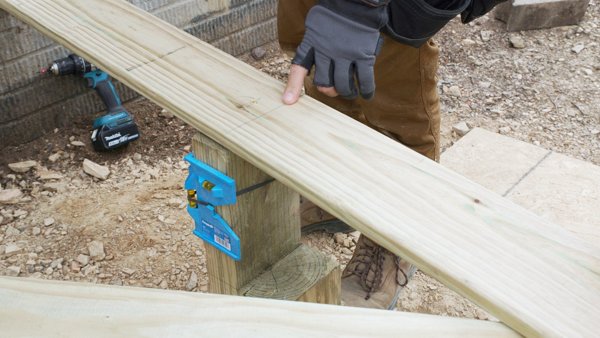
Step 6
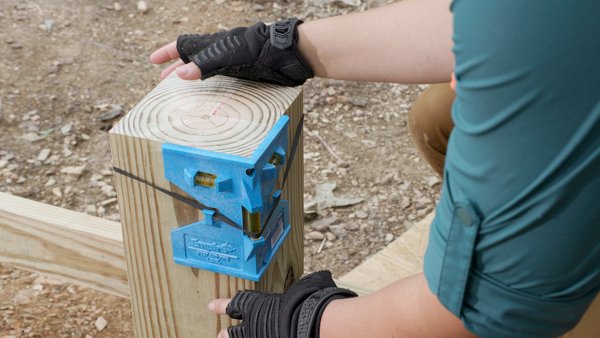
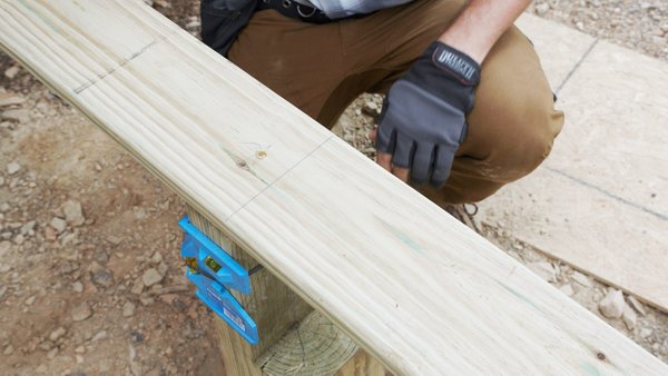
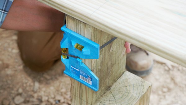
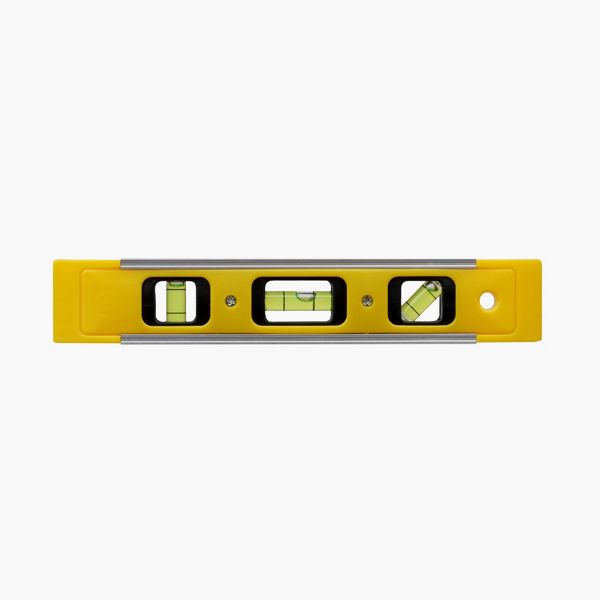
Level the support post in both directions to ensure the post is straight up and down. A post level can be used for simplicity or a longer level may be used on both sides as an alternative. In this case, a post level was used.
The post can now be marked on the bottom of the straight edge. This mark identifies the bottom of the beam material and where the beam will sit on the post. The cut of the post will be determined by the type of beam used. For more information on types of beams, see Chapter 2.
Hold the post against the straight edge material and mark the bottom of the straight edge. This mark is the bottom of the beam.
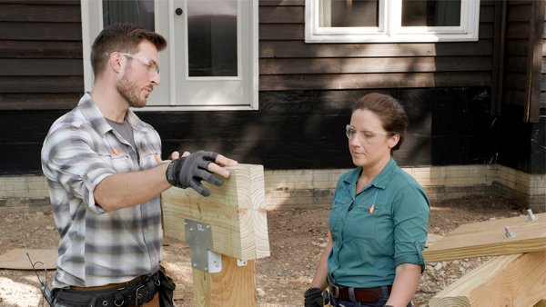
Beam connections (i.e., post-to-beam connections) are code-enforced, because they provide critical connection points for the deck frame. There are different types of beam connections that can be used, so check with your local municipality for approved connections to ensure code compliance. An important piece of criteria to look for in a post-to-beam connection is that the beam is fully supported by the post. This means the beam must be attached to the post in a way that prevents it from shifting off of the post in an unforeseen circumstance while also ensuring that it remains straight. Here are some connections that are approved in most areas:
A. A double beam on top of a 4x4 post with Simpson AC4Z post-to-beam connector and LPC4Z post-to-beam connector on the backside of the beam. Exterior rated Simpson Strong Tie SD connector screws are used to fasten the brackets to the post and beam. Check Simpson Strong Tie guide for correct sizing of fasteners.
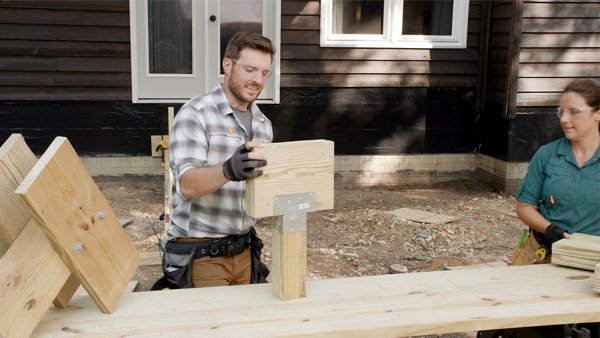
B. A double beam on top of a 6x6 support post. Attached with a Simpson Strong Tie AC6Z post-to-beam connector on the front side and an LPC6Z post-to-beam connector on the backside. Exterior rated Simpson Strong Tie SD connector screws are used to fasten the brackets to the post and beam.
C. A triple beam on top of a 6x6 support post. Attached with a Simpson Strong Tie AC6Z post-to-beam connector on the front side and an LPC6Z post-to-beam connector on the backside. Exterior rated Simpson Strong Tie SD connector screws are used to fasten the brackets to the post and beam.
D. A double beam supported on top of a 6x6 support post, notched out for the size of the double beam. The beam is attached to the post with ½”x7” hot-dipped galvanized bolts, nuts and washers.
Step 1
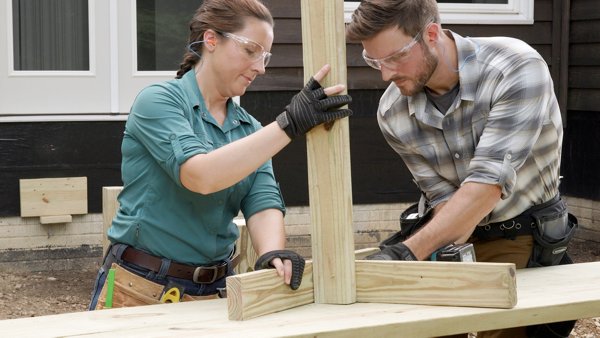
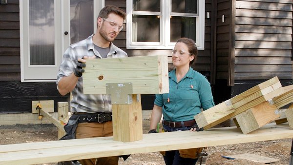
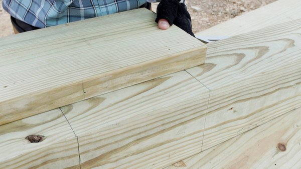
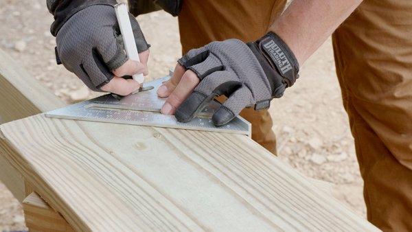
To notch a 6x6 post to support a double beam, start by placing the post on top of sawhorses or a worktable.
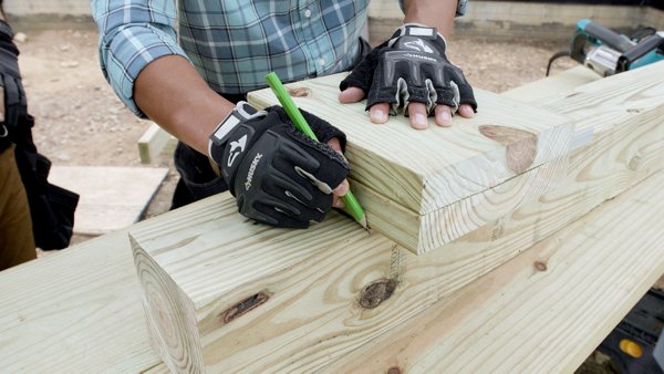
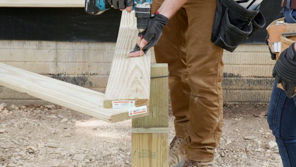
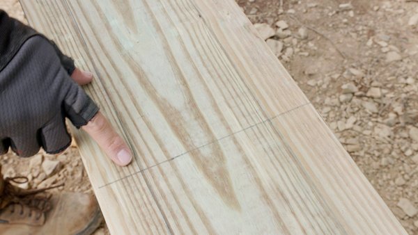
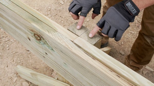
Find the mark that was made by leveling out from the house in Chapter 1 and place a speed square against the post and on that mark.
Slide a short piece of the beam material up against the speed square and mark the post at the top of the beam material. This mark represents the top of the post. The lower mark represents the bottom of the beam and where the notch in the beam will start. In this case, the notches were made for a 2x10 double beam.
Step 2
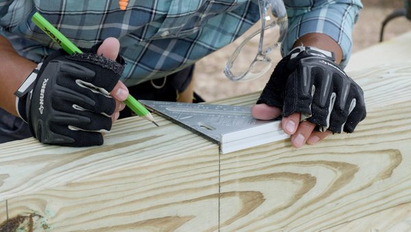
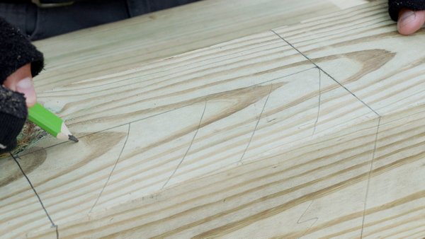
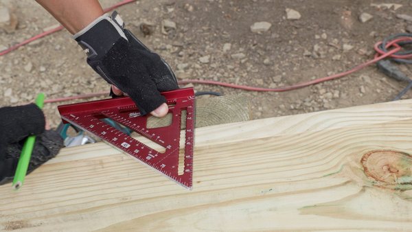
Transfer the marks around the post. Start with the lower mark, which will be the bottom of the notch where the beam will sit on the post, and transfer the mark across the side of the post.
Step 3
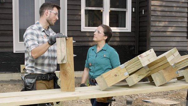
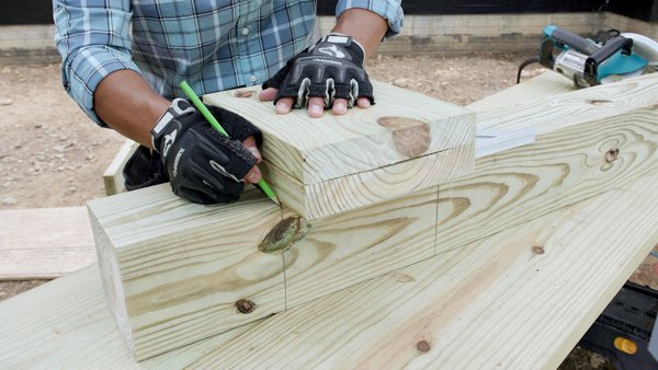
Place a piece of the beam material against the speed square and transfer the line across the post.
Mark the depth of the beam on the side of the post.
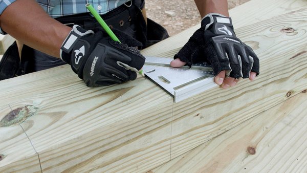
Measure the distance of the beam thickness from the edge of the post with a speed square.
Mark this point at the bottom of the notch. Then, repeat this process at the top of the post.
Use a straight edge to mark the line connecting the two beam depth marks.
This portion of the post will be cut out.
Step 4
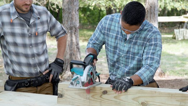
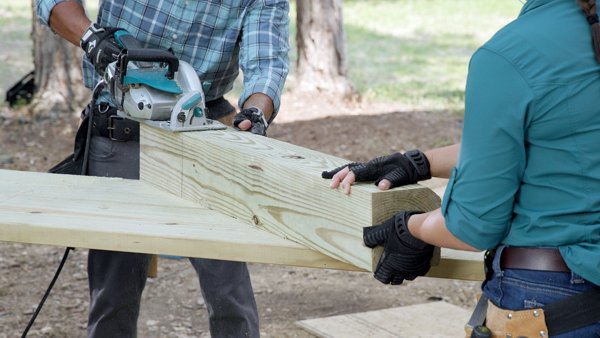
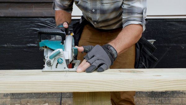
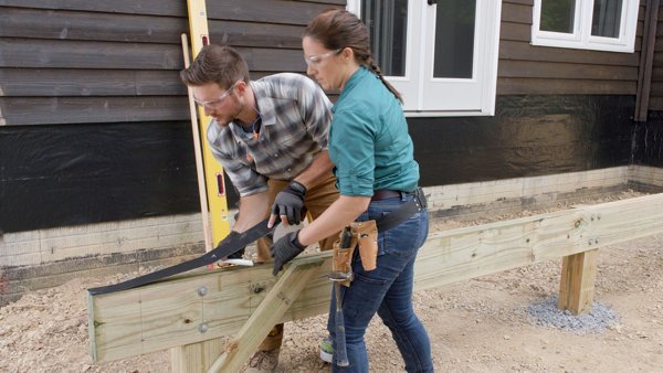
Use a circular saw at full depth to keep cutting the lines around the post made in Step 3 to keep the cuts straight and even.
Cut the top of the post first and be sure to cut all the way around the post with the circular saw. The remainder of the post in the middle can be cut with a reciprocating saw or a hand saw. Be sure to follow the manufacturer's safety instructions.
Step 5
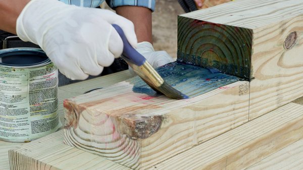
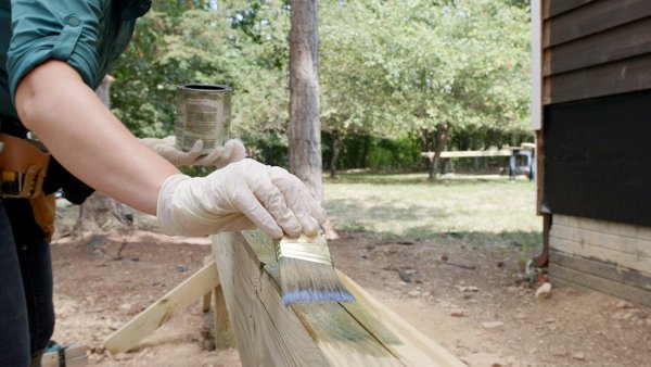
Treat all the cut edges on the post with a wood preservative. Repeat this process for all posts that have a notch to accommodate the beam.
Step 1
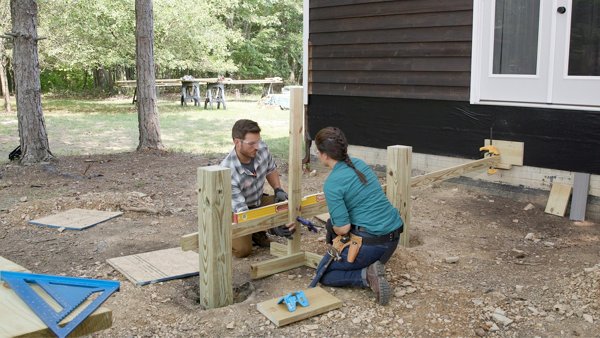
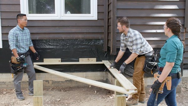
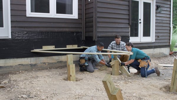
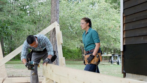
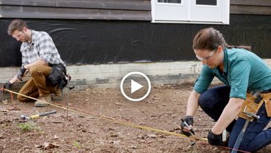
Using the “3, 4, 5 method” to square a corner, you can determine a 90-degree angle off the house where the edge of the deck will be. To use this method, measure 3 feet from the edge of the house and 4 feet away from the house to create a diagonal measurement of 5 feet. In this instance, a line or straight edge would be used to measure 4 feet.
Move the line on the 4-foot side as needed to line up with the 5-foot mark. Once the diagonal measurement is at 5 feet, there will be a 90-degree angle off the house. This means the deck will be square with the face of the house. In this instance, a large triangle was built to show the 3, 4, 5 method and give a structure to hold the post. The large triangle acts as a bigger speed square, has a 90-degree angle, and is fastened together to stay in this form.
Step 2
Attach the speed square to the house. This gives a 90-degree angle off the house to line up the post with the edge of the speed square.
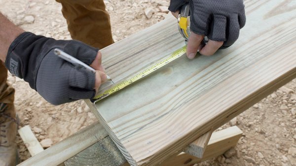
From the house, measure the distance for the beam. This will be notated on the deck plans.
Mark this point on the speed square and align the post to the mark.
Step 3
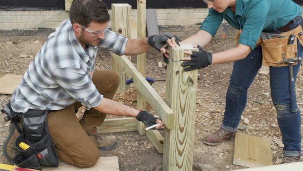
Fasten the post to the speed square with a temporary fastener. Do not tighten the fastener all the way so it can easily be removed later in the installation process.
Plumb the post in both directions so it is perfectly straight. A post level can be used, as in the video, or a short level can be placed on each side.
Fasten temporary braces to the sides of the post to keep it plumb (i.e., vertically straight), and remove the large speed square.
In the case where a beam splices on top of a post—meaning the beam is not one long piece but two pieces and the two ends meet on a post—measure the distance on the house from the edge of the deck for the length of the beam. This is usually notated on the deck plans.
Step 4
Attach the large speed square to the house at the mark made for the beam placement.
Place the support post under the speed square.
Place the post at the appropriate distance away from the house according to the deck plans with the edge of the speed square in the center of the post. Attach the speed square to the post.
Step 5
Plumb the post and fasten temporary braces to keep the post in place.
Repeat this process on the remaining posts.
Some posts will be attached to the speed square in the middle of the post, some will be attached to the edge of the post, and some will be attached to a specific measurement from the edge of the beam. Check your deck plans for specific locations.
Step 1
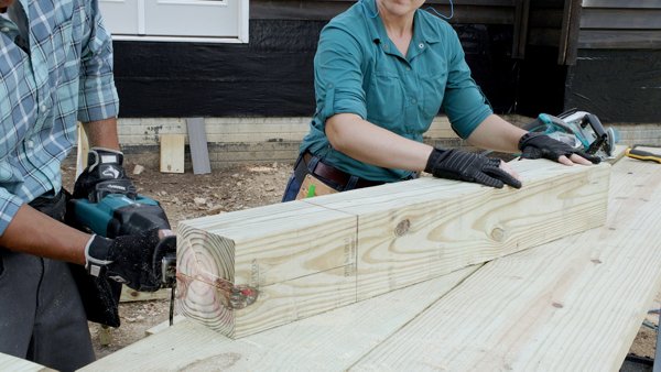
Be sure to have the beam flush with the edge of the first post and place the first piece of beam material into the notches of the posts.
Transfer the center mark of the post through the beam material.
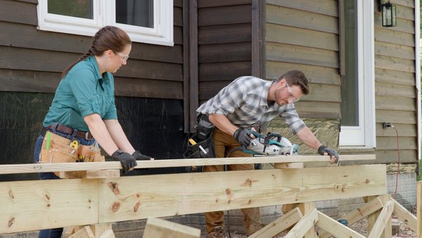
Place the beam flat on top of the posts and cut the piece of the beam at that mark using either a circular or reciprocating saw.
Step 2
Place the cut piece of the beam in place and tack the beam to the post with 3” exterior grade wood screws. Make sure to install the fasteners closer to the top and side of the beam to avoid the permanent fasteners hitting them.
Measure the next piece of beam material and cut it to length–repeating Step 1. Place the beam in the notches of the posts and tight against the other side of the beam. Tack the beam in place using the same 3” exterior-grade wood screws.
Step 3
Set the second ply of beam material on top of the notches and tight to the first ply of beam material.
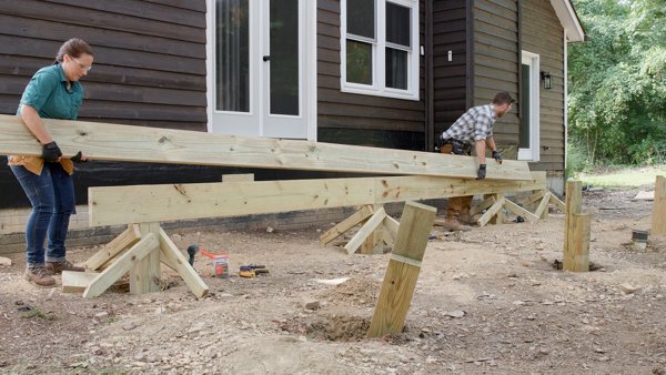
Push the beam until it is flush on the end with the first ply of the beam. In this case, the total beam is longer than 20 feet, so the beam was installed in shorter pieces.
Make sure the second ply of the beam does not get spliced on the same post as the first ply. By alternating the splices, the beam will stay straighter and more rigid. All splices of the beam must be done on top of a post.
Step 4
Mark the beam by transferring the centerline of the post to the beam.
Place the second ply beam on top of the posts and the first ply beam.
Use small scrap pieces of lumber under the second ply beam material to leave a space between the two. This ensures that when the material is cut, the saw will not cut into the beam or post underneath.
Cut the second ply beam material.
Step 5
Fasteners will be installed to connect the two pieces of beam together, making them one unit.
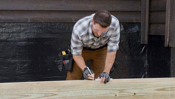
To find the placement of the fasteners, start by marking down the edge of each side of the beam. In this case, the fasteners need to be two inches from each edge.
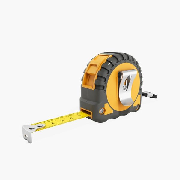
Using a measuring tape, mark the fastener placement from the edge and use a speed square to drag a pencil along it to create a straight line at 2” from the edge of the beam.
Check with your local municipality for proper placement of the fasteners.
Step 6
Transfer the mark made in Step 5 across the board using a speed square.
Pull a tape measure from this mark and mark every 16”. In this instance, two fasteners were required every 16” when fastening two-ply beams together.
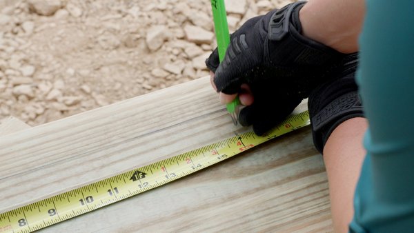
Transfer the marks made at 16” on center across the beam material. Each spot where the marks intersect represents where a fastener needs to be installed.
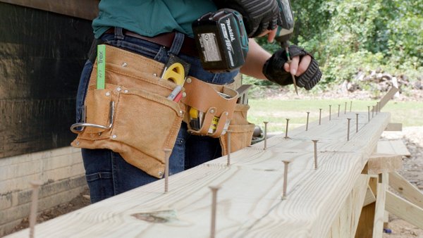
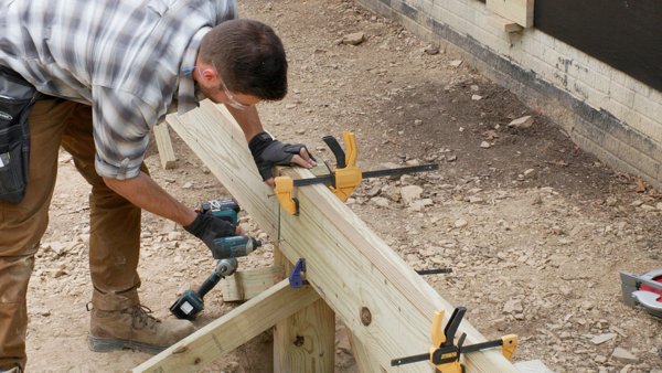
Step 7
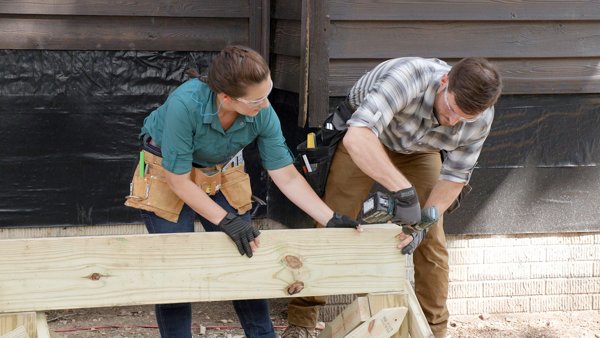
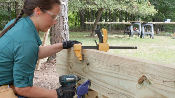
With the beam material still flat on top of the posts, start the fasteners into the material but do not drive the fastener all the way through. Starting the fasteners now will make it easier when the second ply is placed next to the first ply.
Place the beam material on top of the notched post and tight against the first ply of the beam. Clamp the two pieces together using a bar clamp and screw the fasteners through the two pieces of beams.
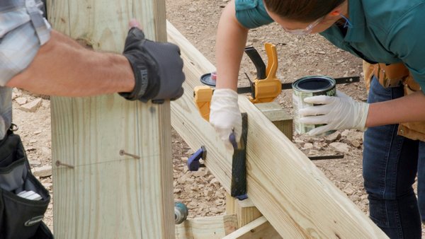
Make sure all cut ends are treated with a wood preservative before final assembly.
Measure and cut the last piece of beam for this section. Install this piece in the same fashion as the first.
Step 8
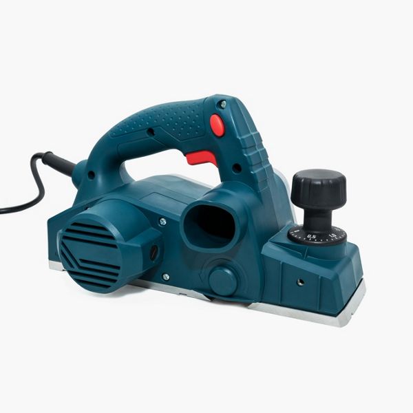
The two pieces of beam material may not be the same width. To even the two pieces of beam material out and make them the same width, mark the high spots and use a planer to plane them down.
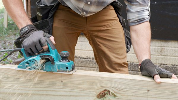
Take a little at a time and go back over the spot if needed. Be sure all cut ends are treated with a wood preservative.
Step 1
Transfer the centerline of the post to the face of the beam. This will be the mark where the fasteners are placed.
In this case, the fasteners need to be located 2” down from the top of the beam and 2” up from the bottom of the beam. These marks were made on the beam during Chapter 5. The holes for the beam fasteners should be placed where the 2” lines intersect with the centerline of the post. When using a longer drill bit, make sure the drill and bit are level to ensure the bolt goes straight through the beam and not at an angle.
Step 2
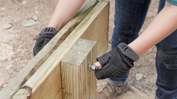
To install each fastener, insert the bolts, with a washer, through the beam and post.
Attach a washer and nut to the end of the bolt. ½”x7” hot-dipped galvanized bolts were used in this instance.
Check with your local municipality to verify proper fasteners.
Step 3
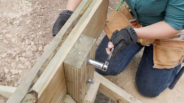
With two wrenches, one on each side, tighten the bolts until the washer indents slightly into the wood. An impact driver can be used in this case, and an adapter to fit a socket will be needed.
Hold the bolt side with a wrench and use the impact driver to tighten the nut. In this case ¾” sized wrenches were used with ½” bolts.
Step 4
There will need to be four bolts where the beams splice on a post. In this instance, ½” x 7” bolts were used.
Find the center point of the post, then find the center point of the two sides of the post. In this case with a 6x6 post, measure 1 3/8” from each side of the post and make a mark.
Transfer these lines down the front of the beam. Holes will need to be drilled where these lines intersect the 2” lines from the beam fasteners.
Repeat this process for all post-to-beam connections.
For decks with multiple beams, this process can be repeated by attaching the large speed square to the installed beam, measuring and leveling the posts of the next beam.
Step 5
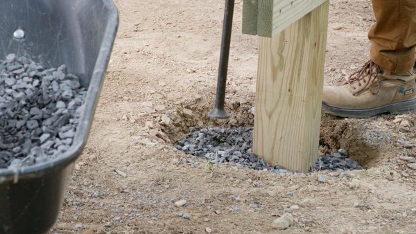
With the post and beam attachment complete, it is necessary to backfill the hole around the post for stability. In this case, gravel was used to fill the hole.
Place the gravel around the post in layers and tamp the gravel at each level. Repeat this process until the hole is filled.
Check with your local municipality to see if other materials, like soil or concrete, are code-approved.
Step 1
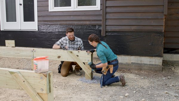
Lateral bracing is installed to keep the deck from shifting when a large weight distribution happens by keeping the posts at a 90-degree angle with the beam.
2x pressure treated material should be used per code. A minimum 2x4 should be used and attached to the beam with an exterior rated fastener. Check with your local municipality for code-approved fasteners.
Step 2
Attach lateral braces on the corner support posts only. Do not install on center support posts.
Install Trex® Protect™ beam tape over the multi-ply beam. This helps prolong the life of the beam by not allowing moisture in between the beam pieces, which could rot the material from the inside. In this case, 3” tape was used to cover the wider double 2x10 beam.


Materials
3" Exterior-Grade Wood Screws
Exterior Rated Simpson Strong Tie SD Connector Screws
Gravel
1/2" x 7" Hot-Dipped Galvanized Bolts with Washers and Nuts
Simpson Strong Tie SD Connector Screws


MADE IN THE U.S.A.
Copyright © 2024 Trex Company, Inc. All rights reserved.
Photos and videos © 2024 Warner Bros. Discovery, Inc. or its subsidiaries and affiliates. All trademarks are the property of their respective owners. All rights reserved.


By choosing your country, you acknowledge that you have read Trex's Privacy's Policy
Are you in the USA or Canada?
By choosing YES or NO, you acknowledge that you have read Trex's Privacy Policy